NET3001 Teaching Board
MTS2: microcontroller training system
motivation
current status
design
teaching opportunities
notes on the hardware design
Motivation
For the last few years I have been teaching a course in real time
programming. The 3 month course consists of
- assembly language programming
- C programming
- interrupts
- cooperative multitasking
The students write code on an embedded microprocessor. Previous versions
of this course use the HC12 and the MSP430.
I wanted to create a course where the students could bring the
development system home, and work with their own PC. That meant:
- open source tools
- a small portable development system
- lowest cost (including development tools)
To demonstrate the various aspects of the course, the board must have:
- a variety of easy-to-understand peripherals, with user interaction
- interrupts and real-time-clock
Current status
I have designed this
- a 6"x4" board, fits inside a VHS cassette case
- an ARM/Cortex-M3 CPU with 128kB of flash, 8kB of ram
- a programming port, which allows download and in circuit debugging
- peripherals
- LCD display, 130x130 pixels, RGB with backlight
- 12+1 button keyboard
- microphone
- beeper
- DC motor
- stepper motor
- servo motor
- 8 LED's
- one digit 7 segment display
- joystick
- temperature sensor and colocated heater
- light sensor
- thumbwheel
- two light sensors
- socket for microSD card
- 2-way radio module
- accelerometer (tilt sensor)
- UART/serial back to the host CPU
Here's a photo.
Design
CPU
I wanted the CPU to be easy to teach, and I wanted to move up to 32 bit.
That points to the ARM processors, and the Cortex in particular, which are
at a great price-point.
Debugging
The CPU needs to allow easy download and single stepping, as well as
the ability to view registers and control I/O ports. Again, the Cortex
processors do that well.
Power
Almost all the chips on the board run at 3V or 5V, so a USB cable can
provide all the power. The backlight on the LCD requires +7V, and the RS232
requires +/-7V; the MAX232 chip can generate both of these.
In order to run the servo motors, however, we need a lot more current, so
the board has a LiPo battery 150mAH which provides the surge current
required by the servo motor.
Radio
The students in the course are also learning about network protocols in
their other courses. So this board has a 2.4GHz radio transceiver. This
unit is low cost, only chews about 10mA when it's running, and has a
full packet fifo and MAC features (preamble, header and CRC assembly).
The students can either use it at this level, or introduce a link-level
protocol. The packet payload can be up to about 25 bytes, or even more
if the CRC & address fields are reduced.
Motors
There are three motors on board. The DC motor is driven by two PWM pins,
which allows us to speed it up and slow it down, and even reverse it.
The stepper motor is a 4 pin unipolar drive, so the drive sequences are
A...A...A...
.B...B...B..
..C...C...C.
...D...D...D
or

AA.....AAA......
.BBB.....BBB...
...CCC.....CCC..
.....DDD.....DDD
Both should be fairly easy to teach.
The servo motor requires 1.5msec pulses every 20msec. Teaching this will
be a challenge, and we may not get to it in the basic course.
Cost
Provisional: CDN$40 for parts. Labor will probably be me-&-free.
Many of the parts are coming from surplus houses, HongKong eBay and Digikey.
Teaching Opportunities
Some assignments which I am considering
- light up the LED's
- read the temperature
- scan the keyboard
- connect keystroke to an LED
- report keystrokes to LCD
- measure human reaction time from beep-to-keystroke,
beep-to-handclap, led-to-keystroke, led-to-handclap
- build a frequency meter to measure audio frequencies
- build an echo-locater (ultrasonic click on the beeper to
microphone delay)
- spin the motor
- send data through the radio
- build a mesh network using the radios
- simulate
- car wash
- traffic lights
- car radio
- vending machine
There are several opportunities to teach physical feedback:
- temperature sensor has a colocated heater; target: set constant temperature
- servo motor arm swings down and covers one of the light sensors:
target: move the servo for constant light flux onto sensor
- armature of the DC motor spins over the IR light sensor: target:
set the rotation speed of the motor
Hardware design notes
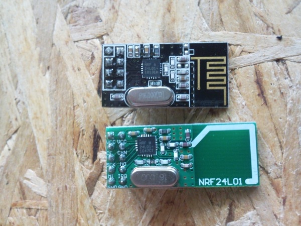
- nRF24L01 modules
There are two designs for this module: an 8 pin and a 10 pin. My board
is designed for the 8 pin version. But I had a hard time getting it to work;
it turns out that the module is sensitive to glitches on the rails, and my
board wasn't well designed to feed power to the module. A 10uF cap across
the rails at the module fixed it.
I was accidentally sent 20 modules of the 10 pin variety. Fortunately, 7
of the 8 pins line up, so the mod was trivial to get the 10 pin versions to fit.
This module is not as sensitive to glitches on the rail; I assume
there is on-module filtering.
- Servo motors
I ordered the 9g motors that are designed for model helicopters. Of course,
the samples I got consumed 3mA when idle and 60 mA when active. But the
production quantity consumed 6mA when idle, and peaks of 300mA when active.
This forced me to add a LiPo battery as a mod, in order to supply enough
current to the motor. In hindsight, I should have dropped the motor from the project.
- Accelerometer
I'm using the MMA8453. Be warned that this chip does not neccessarily power
up in a clean state; you must perform a software reset before using it.